

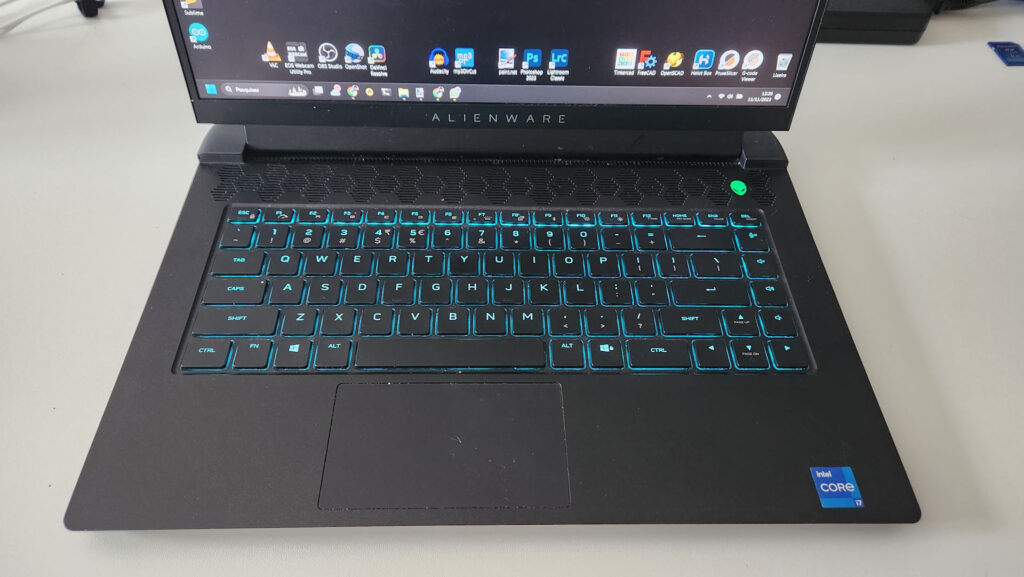
For a long time, now, like every self-respecting DIYer, I have been rescuing, from any electronics device, everything that can be used later in some other project. 18650 li-ion batteries are no exception. Over the past 10 years, I have rescued between 30 and 40 batteries from old laptops that were damaged or were simply replaced with newer / better models. However, as the batteries have already been somewhat used, they certainly do not have the original capacity they had when left the factory. So, before using them in other projects, it is always important to check how much charge they can store and, thus, assemble sets with a similar charge, maximizing their performance. Furthermore, this tester is also very useful for confirming that new, recently purchased batteries, meet their charging specifications (you never know – there are a lot of scamers in the market…).
18650 Batteries
Before jumping into the project itself, it is interesting to give a brief description of the famous 18650 batteries.
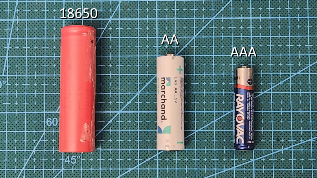
To summarize in one sentence, 18650 batteries are Li-Ion (lithium-ion) batteries, measuring 18mm in diameter x 65mm in length. But, what does the “0” means? Nothing, really. I guess it’s the for “the looks” ;-).
The “nominal” voltage is 3.7V (which is the approximate value supplied for the longest time) but, in practice, it varies from approximately 4.2V (fully charged) to 3.0V (when discharged – they can go lower, but it’s not advisable as it reduces the lifespan of the battery).
The charge they can store (when new) varies from approximately 900mAh to 3600mAh and they can provide peaks of up to 7A of current (this largely depends on the brand and quality).
In general, the durability of these batteries is 300 to 500 cycles, that is, 300 to 500 complete charges and discharges cycles.
It is important to recognize that the values above (except physical measurements) can vary greatly depending on the quality of the battery (manufacturers) and its lifespan (number of cycles used).
Re-Using the Batteries
Okay, this is all very interesting, but what can these batteries be re-used for?
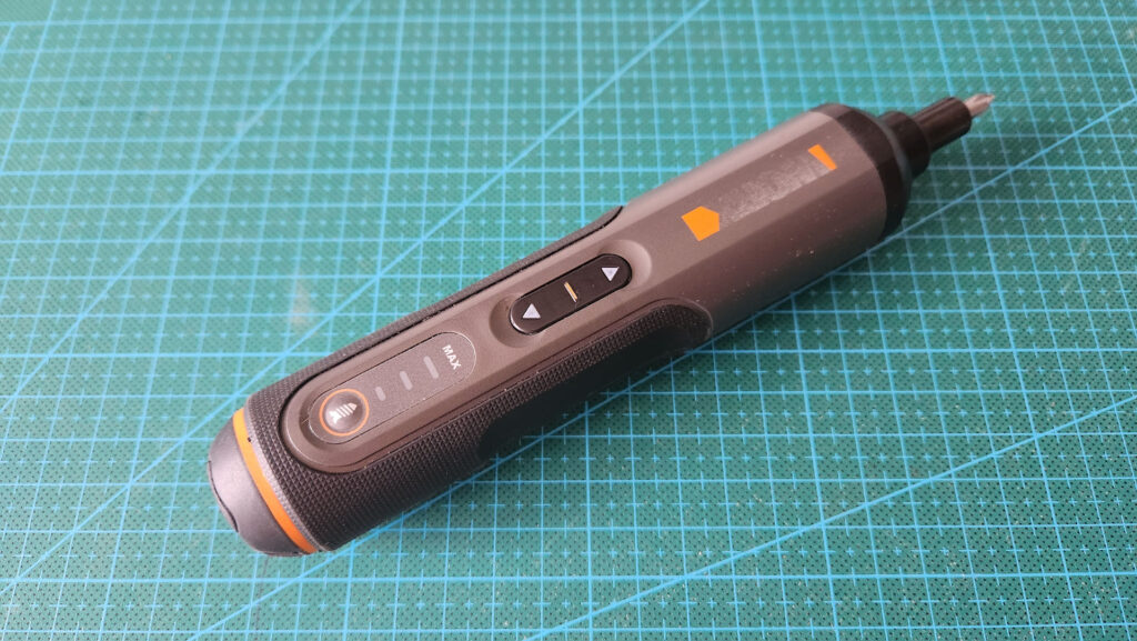
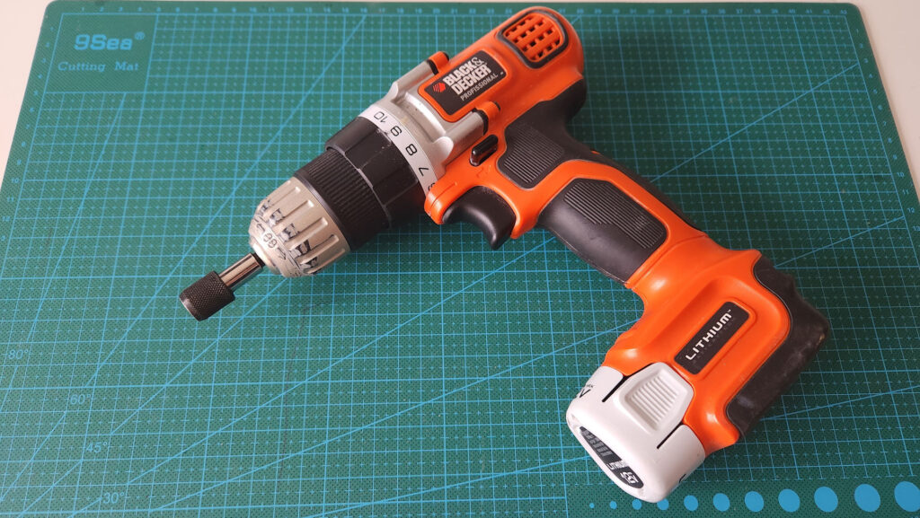
Nowadays, there are countless cordless devices, and this seems to be an increasingly consolidated trend in the industry. If you like making repairs, assembling and everything else, you may have already seen or even used cordless tools, such as screwdrivers, which are the most common ones. But regardless of the product type, they all use some sort of battery and, at the moment, the 18650 is the most common formate given its energy density.
So, possible re-uses of batteries are:
- Repairing damaged battery packs (often, only 1 of several batteries is damaged).
- Assembling additional battery packs for general use.
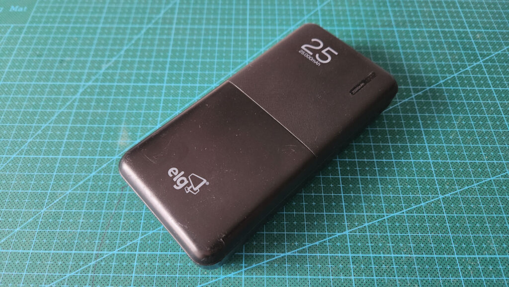
- Assembly energy packs to keep devices (such as internet routers or security cameras) running, even during power outages (small “UPS”, so to speak).
- Creating your own cordless tools.
| IMPORTANT: Re-use Li-Ion / 18650 batteries AT YOUR OWN RISK |
|---|
| -> 18650 batteries have a high discharge capacity and, therefore, if placed in a short circuit they can heat up and catch on fire / explode. -> Li-Ion batteries, due to their chemical composition, can also catch on fire and explode if they get damaged (punctured, sheard, …) |
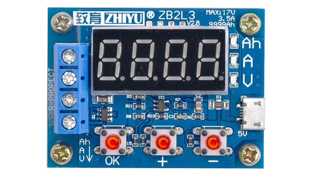
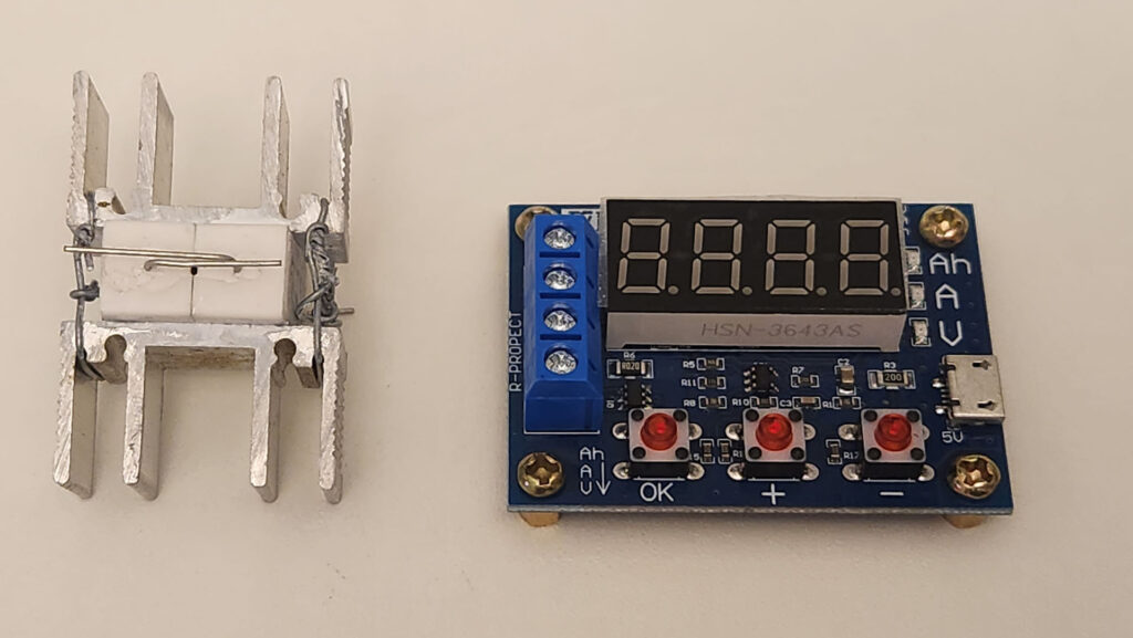
ZB2L3 Capacity Tester Circuit
On the internet, there are many different projects for assembling battery testing circuits without using off-the-shelf circuits or devices (by only using electronic components and an Arduino to control displays and everything else).
However, as the cost of this circuit in particular is quite low (I paid approx. US$ 7.00 – including shipping), it ends up being cheaper than using the Arduino + components, therefore, I decided to opt for this alternative instead.
Thus, the ZB2L3 circuit became the heart of this project. But why this circuit? Are there others?
Yes, on the very same page where I purchased this circuit, on AliExpress (see link below in the “Materials” section), you can choose from a few different models. The ZB2L3 is the cheapest and also the one that gave me the most flexibility when setting up my project.
The operation of the circuit is very simple (after already assembled):
- A previously charged 18650 battery must be connected to the circuit.
- Connect the device to a USB charging device (micro-USB socket).
- Select the cut-off voltage – I suggest 3V: press the (-) button and adjust to P3.0 using (+) and (-).
- Start the process by pressing the button (OK).
- During the process, the circuit will switch between 3 LED indicators:
- Measured capacity (Ah)
- Electric current being consumed at the moment (A)
- Measured voltage (V) at the moment
After these steps, the device will begin to consume approximately 1.1A to 1.2A, which ends up decreasing throughout the test to approximately 0.8A, when the battery reaches the defined cut-off voltage (3V) – when the battery is in good condition.
At the end of the process, the measured capacity value flashes continuously on the numerical display.
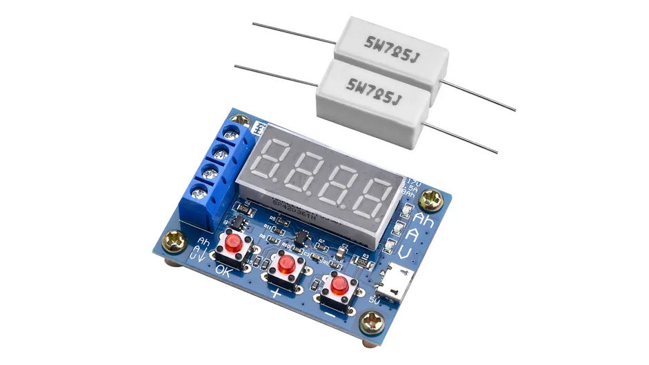
When using a circuit with 2 x 7.5ohm resistors (resulting impedance of 3.75ohm), the consumption starts with a current of approximately 1A, and the discharge time for a 2000mAh battery should be around 2 hours. If only 1 x 7.5ohm resistor is used, the current drops by half and the test time doubles.
Prototype and Capacity Tests
Before working on modeling a case that would result in a device that was pleasant and reliable to use, I needed to test that everything worked correctly.
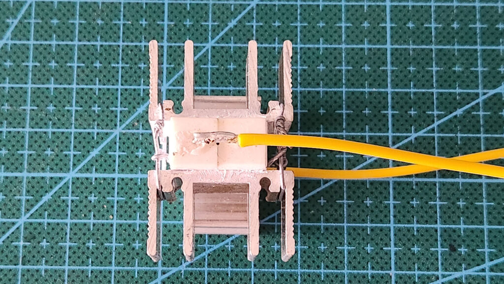
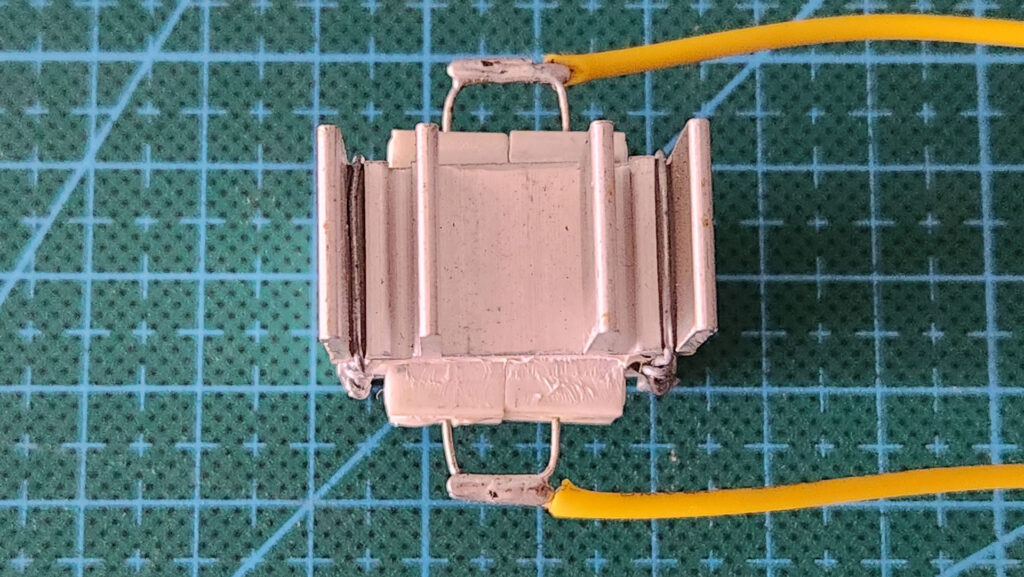
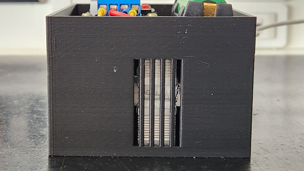
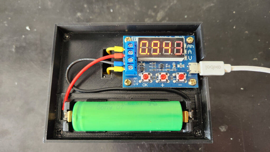
The first detail to pay attention to was that, when using the circuit, the current coming from the battery will be transformed into heat by the 2 resistors. Even though they are high power ceramic resistors, they ended up gettting very hot. So, to prevent them from burning with the heat, I sandwiched them between 2 heatsinks (recovered from old ATX power supplies), using thermal paste and tying everything with thin wire to make it firm. I soldered an electrical wire to each end and added a tubular connector to their oposit ends to get a better finish.
So, I took an 18650 battery socket and soldered black and red electrical wires to both sides, adding tubular connectors at each end of the wires, again for a good finish.
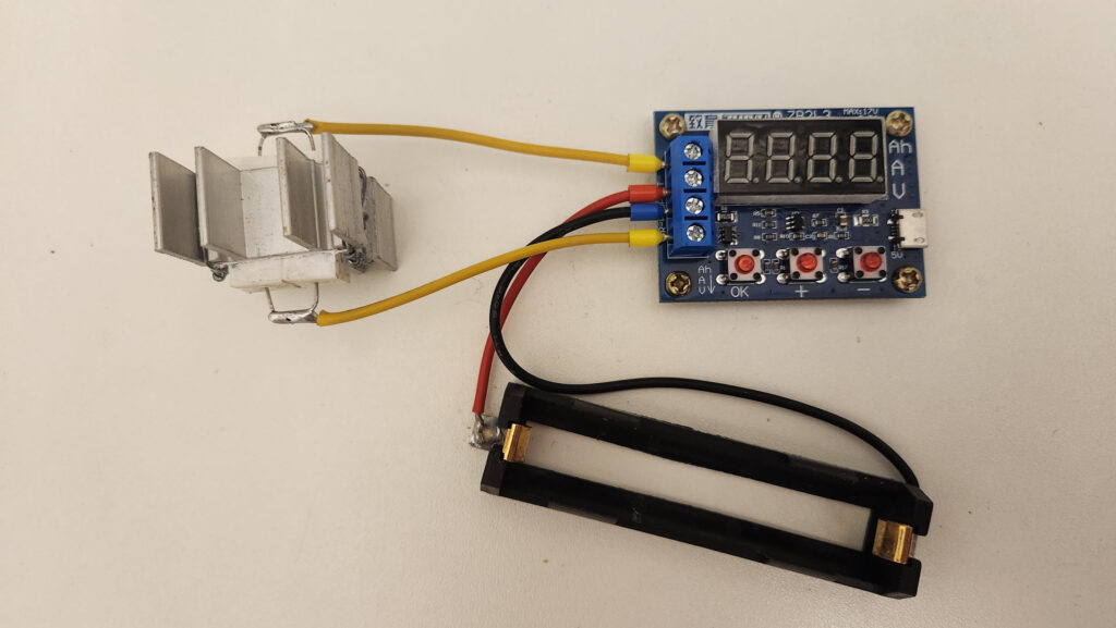
I connected everything and inserted a previously charged battery (this is very important, otherwise only a partial capacity will be measured). And I started the test.
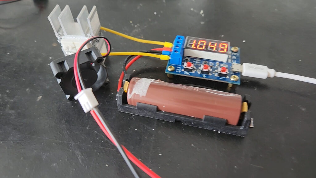
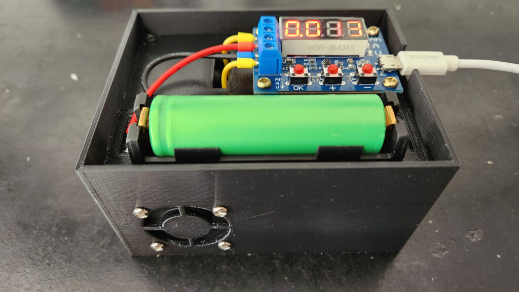
After a few minutes, I realized that, even with the heatsinks, they got quite hot (to the point of almost burning my fingers when touching them), so I added a cooler to blow some air and cool everything down.
| After several tests, I discovered that this circuit is not 100% reliable. The reason may be the discharge speed, or even circuit quality problems. In any case, I recommend doing a second/third discharge at least 1-2 hours apart and without recharging the battery in between. Therefore, consider the battery capacity to be the sum of all discharges carried out. When the test results in approximately 70mAh, you can consider that the battery has already reached its minimum. |
See the results of my tests, using 10 new Samsung branded batteries, recently purchased, with a nominal capacity of 2200mAh:
| Battery # | 1st Test | 2nd Test | 3rd Test | Total Capacity |
| 1 | 2411mAh | 77mAh | 2478mAh | |
| 2 | 2316mAh | 73mAh | 2389mAh | |
| 3 | 2291mAh | 70mAh | 2361mAh | |
| 4 | 2256mAh | 51mAh | 2307mAh | |
| 5 | 2048mAh | 131mAh | 18mAh | 2197mAh |
| 6 | 1725mAh | 403mAh | 27mAh | 2155mAh |
| 7 | 1722mAh | 299mAh | 27mAh | 1880mAh |
| 8 | 1675mAh | 420mAh | 34mAh | 2129mAh |
| 9 | 1641mAh | 329mAh | 46mAh | 2016mAh |
| 10 | 1505mAh | 626mAh | 73mAh | 2204mAh |
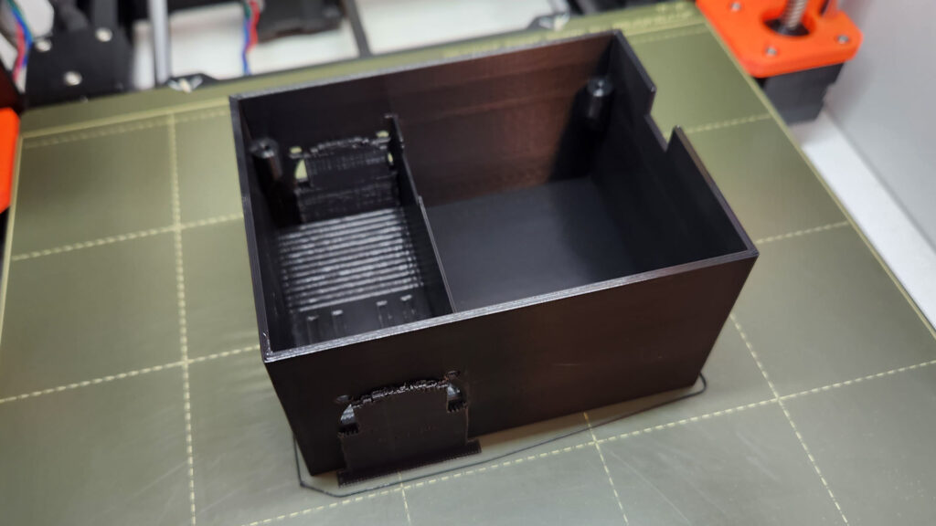
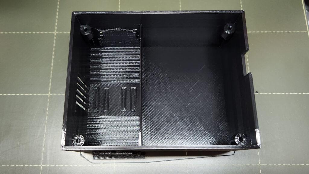
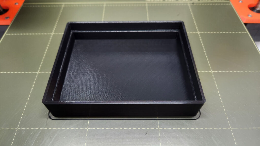
3D Modeling of the Enclosure
To avoid using the components and boards directly, I decided to make a box / enclosure for the project. I then established some requirements:
- It should be as compact as possible.
- It should be detachable, which means attaching the parts using screws (without glue).
- It should be able to be stored with other items without risk of damaging the components.
So, I moved on to the modeling itself, using the TinkerCAD modeler.
You can access the template directly from the dashboard below:
If you don’t wanna change anything, but just 3D print all the objects, please access them at:
https://www.printables.com/model/1283705-zb2l3-capacity-tester-case
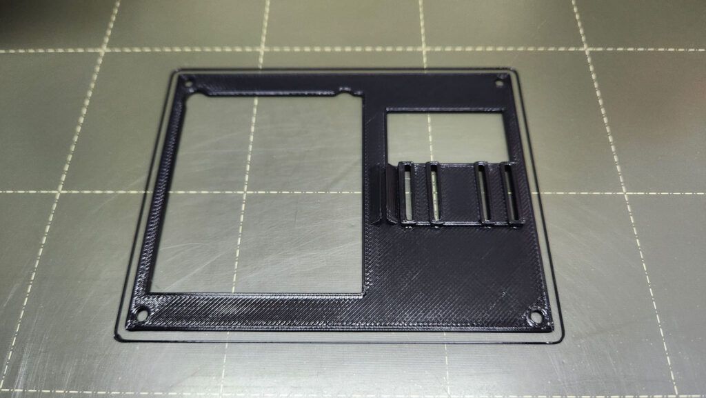
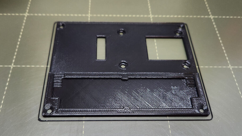
3D Printing
The first step is to slice the objects. No mystery here:
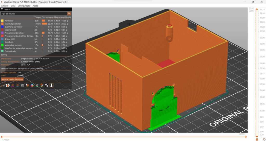
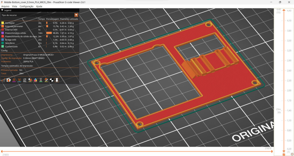
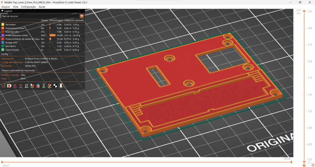
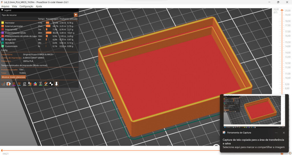
I 3D printed the objects using PLA filament. The total time was 6 hours.
Assembly
Assembly is not complicated, but it requires a lot of hand work (it took me about 2 to 3 hours in total, including welding and testing). The summarized assembly sequence can be seen below:
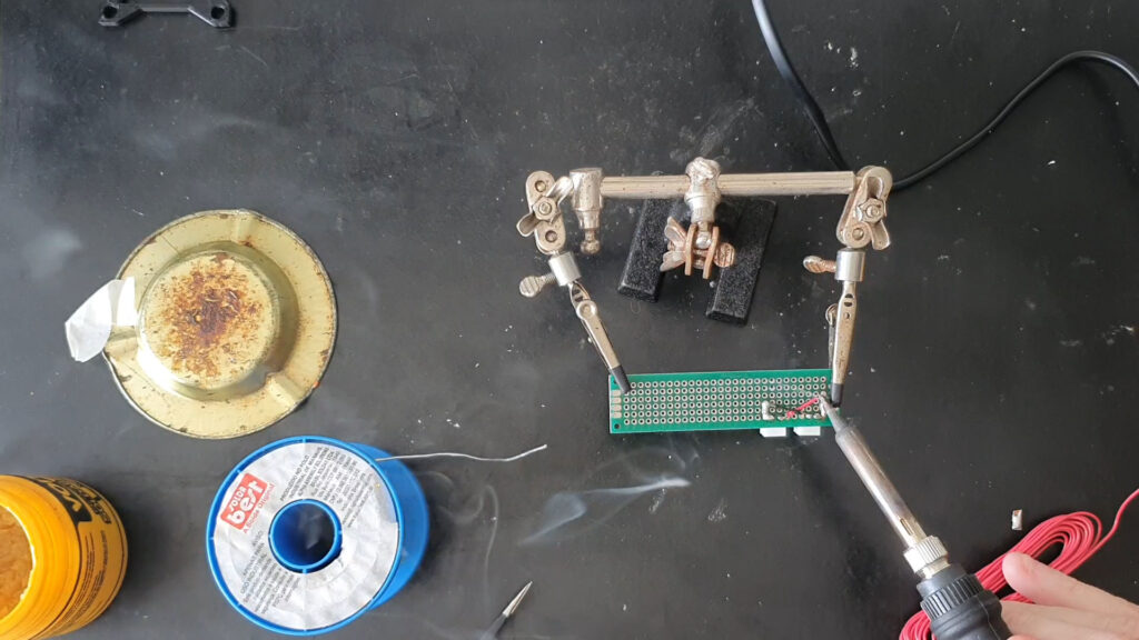
Soldering the cooler power sockets 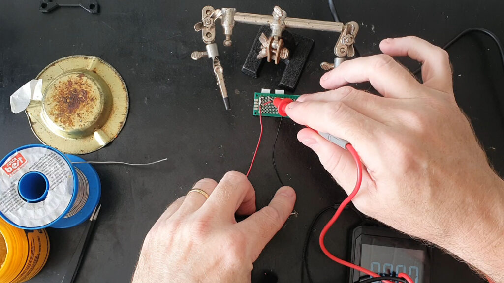
Testing for continuity 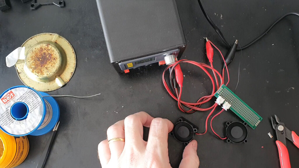
Testing the coolers connected to their sockets 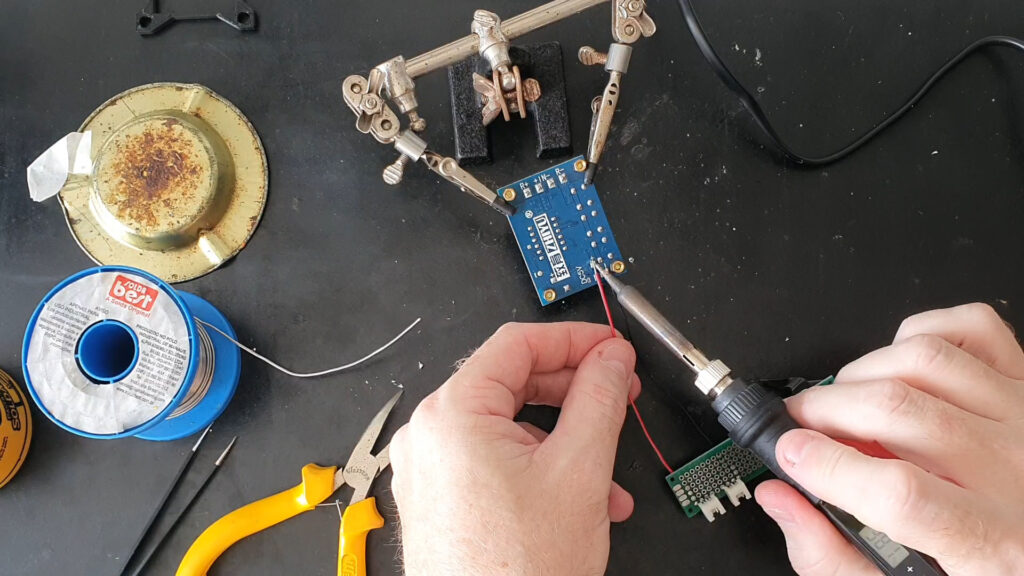
Soldering the coolers wires to the circuit 5V rails 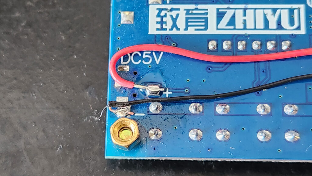
Coolers power wires soldered to the circuit 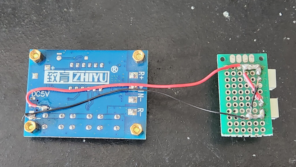
Coolers power set assembled 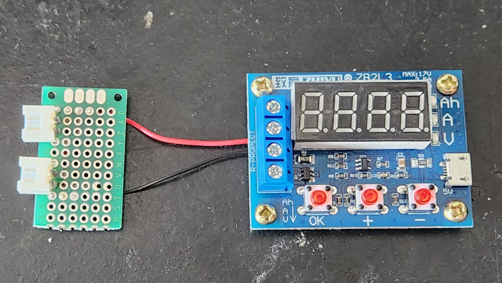
Coolers power set assembled 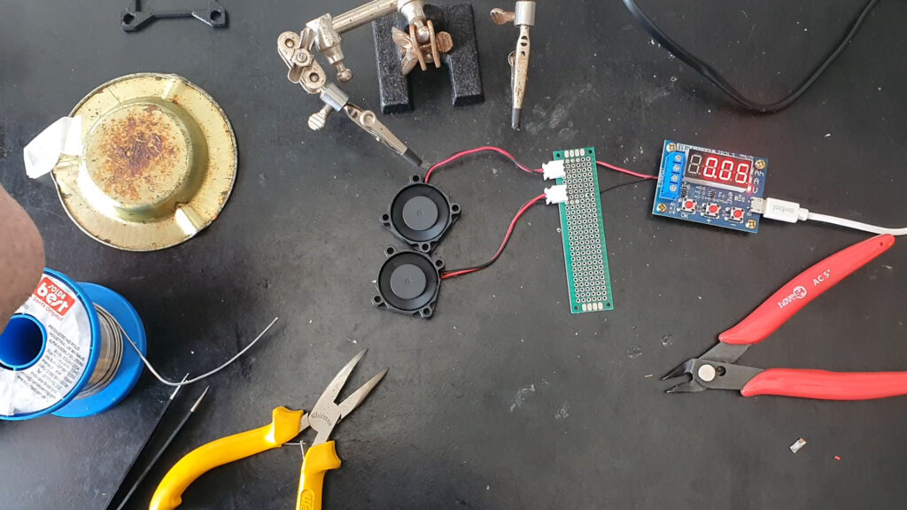
Testing the coolers with USB power from the circuit 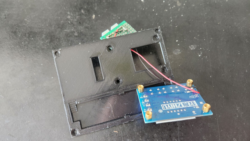
Passing the power sockets through top cover hole 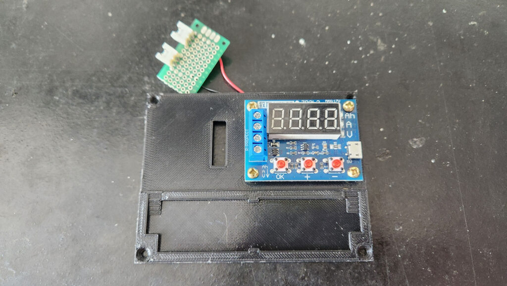
Positioning the circuit on its place on the top cover 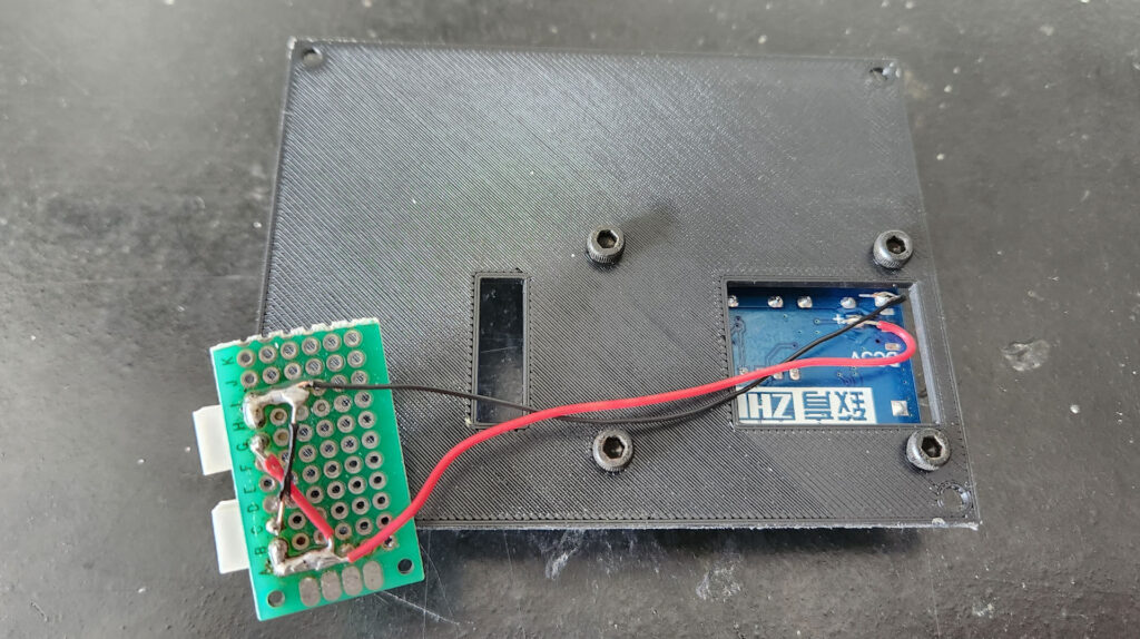
Bolting the circuit to the top cover with M3 Allen 5mm bolts 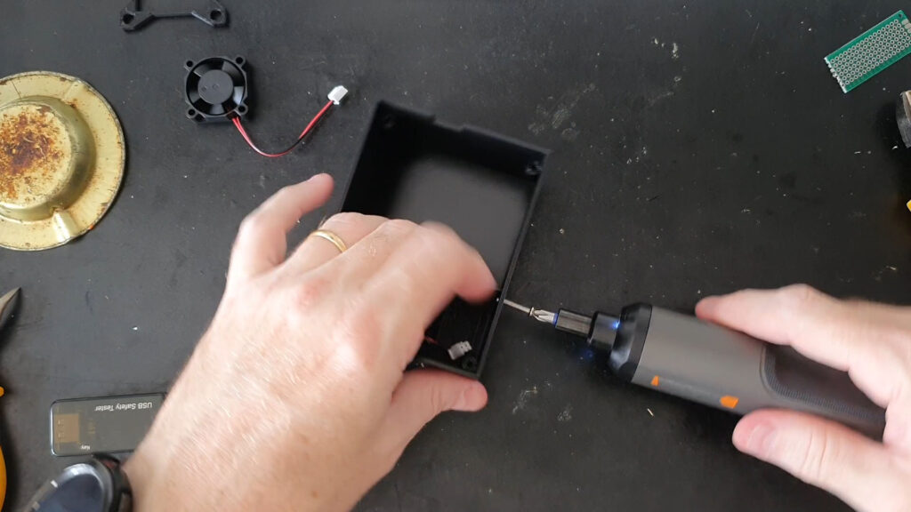
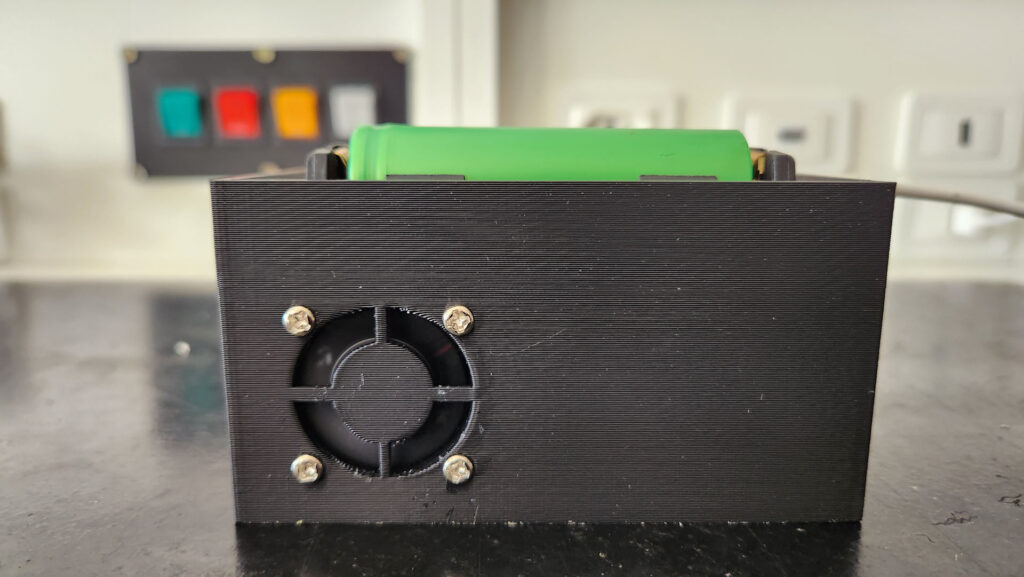
Bolting the intake cooler to the box 
Intake cooler fully bolted to the box 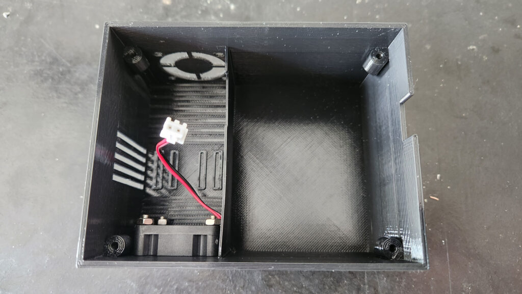
Intake cooler fully bolted to the box 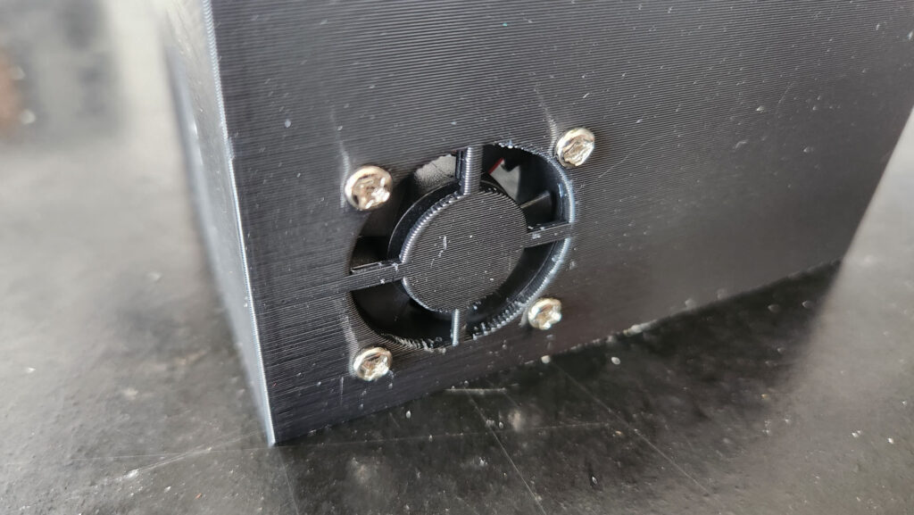
Intake cooler fully bolted to the box 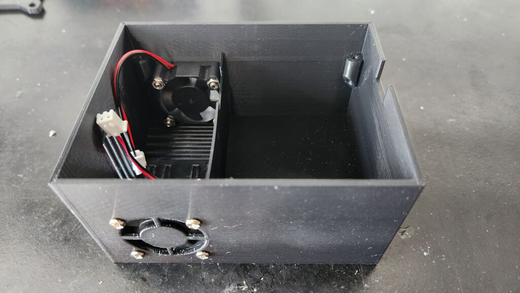
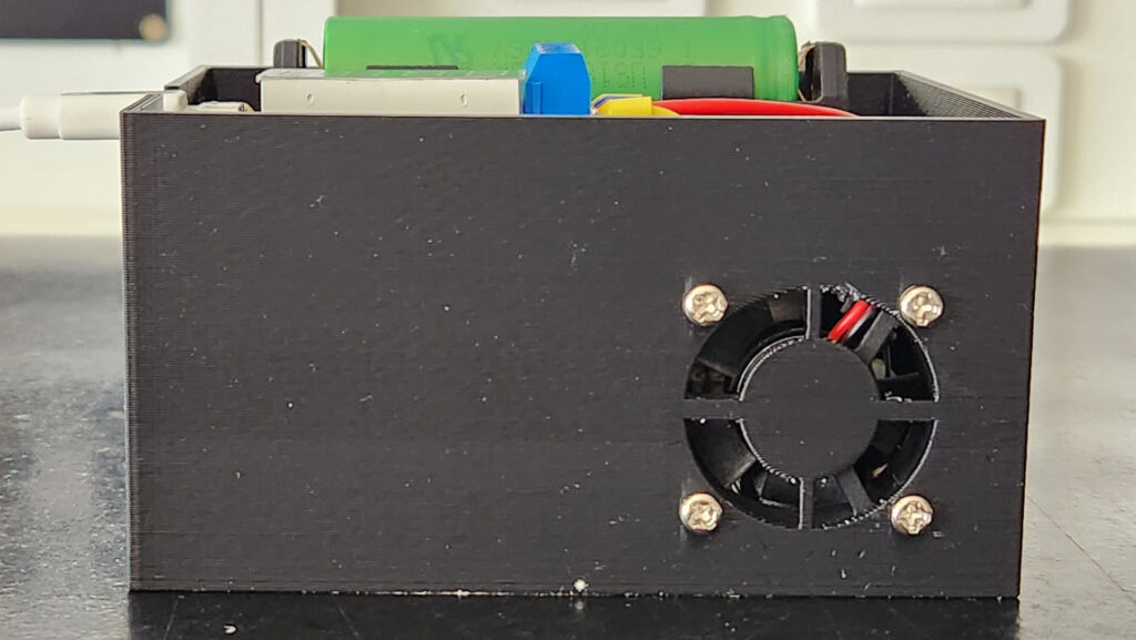
Outtake cooler fully bolted to the box 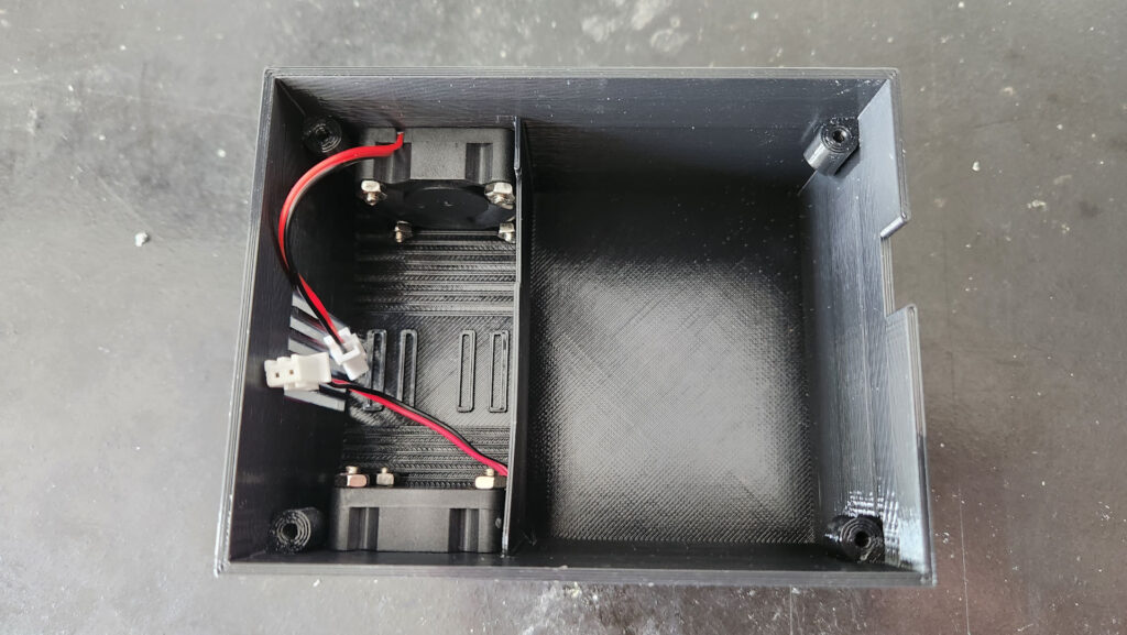
Outtake cooler fully bolted to the box 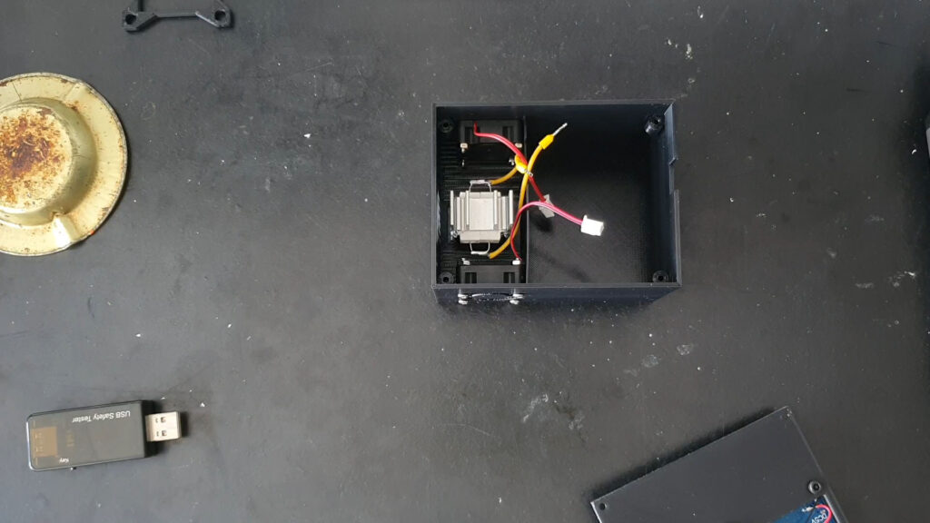
Positioning the heat sink to the bottom of the main box 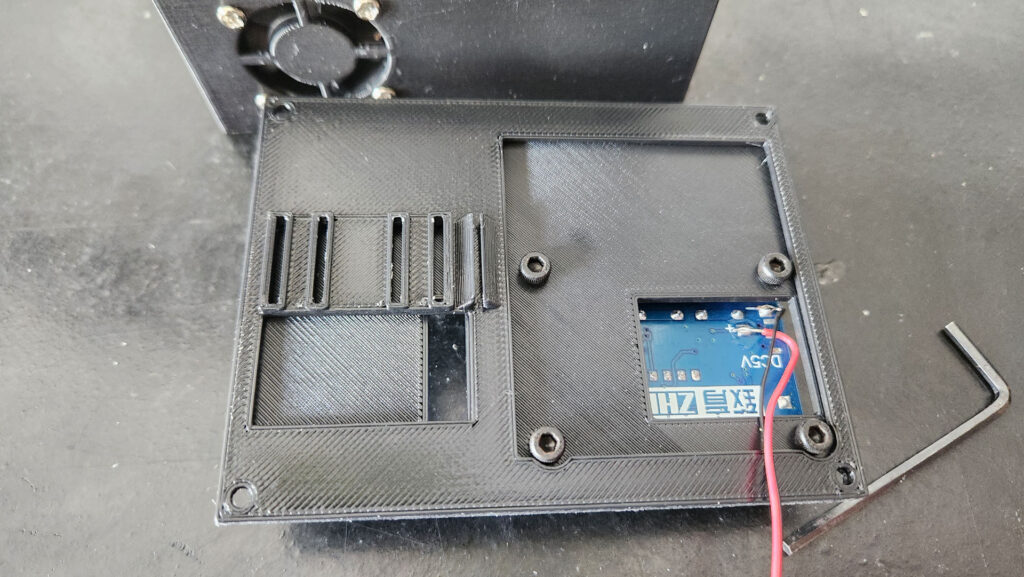
Positioning the bottom cover to the bottom of the top cover 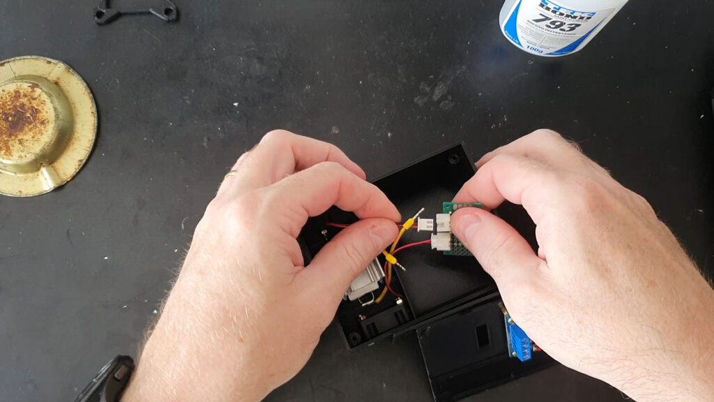
Connecting the coolers power sockets 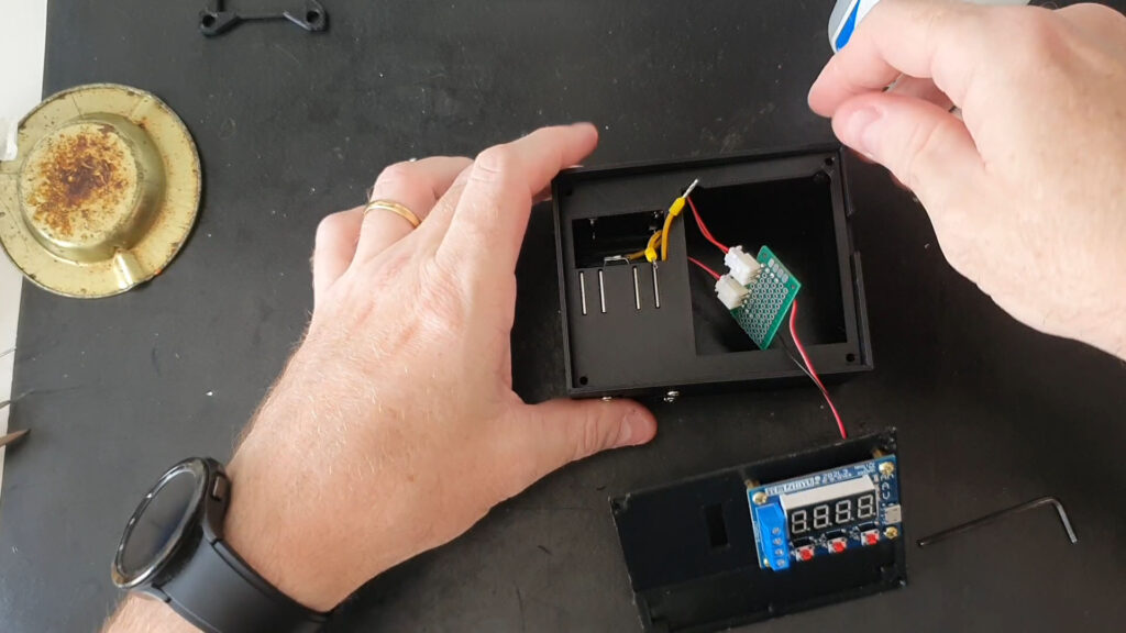
Positioning the bottom cover to it’s place in the main box 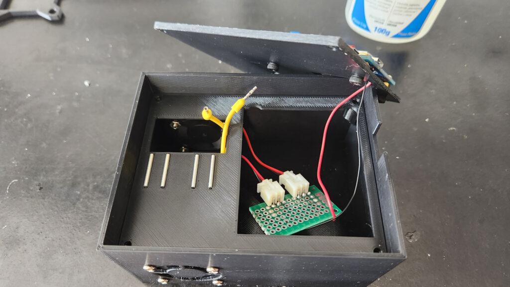
Checking that everything is wired correctly 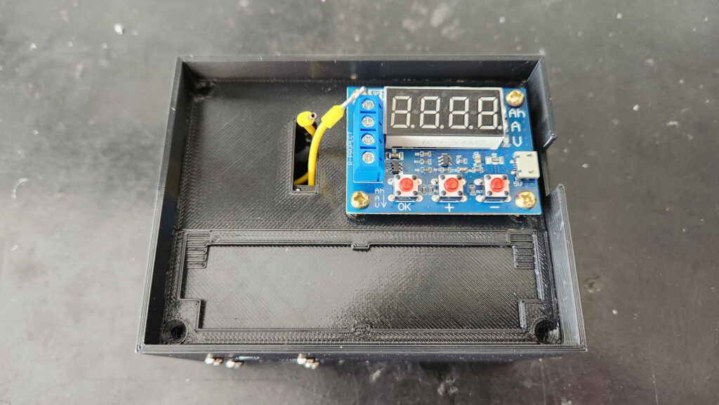
Positioning the top cover to its place in the interior of the main box 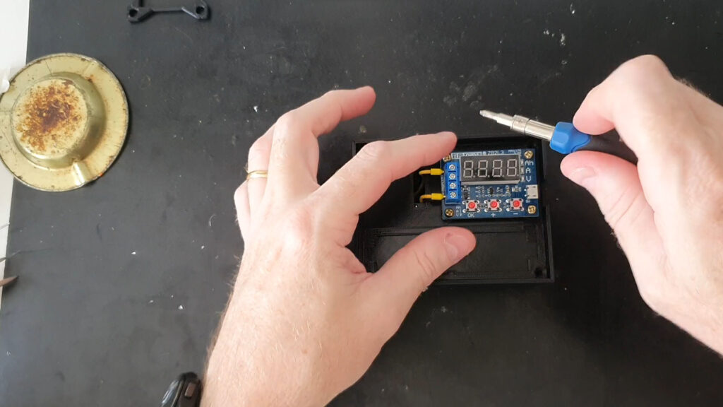
Screwing the resistor wires to the circuit 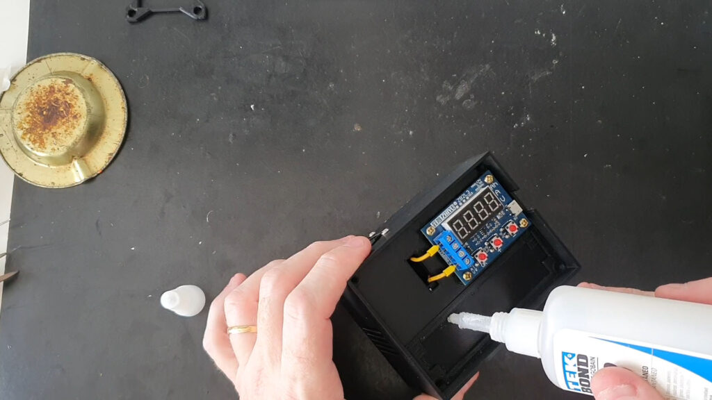
Putting some CA glue to the battery holder recess 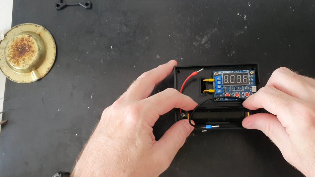
Fixing the battery holder onto its recess 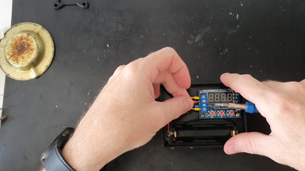
Screwing the battery wires to the circuit 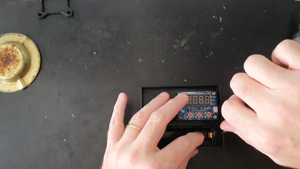
Screwing the top (and bottom) cover onto the main box 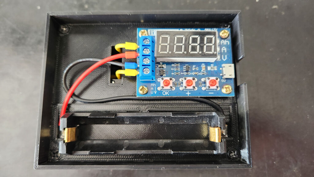
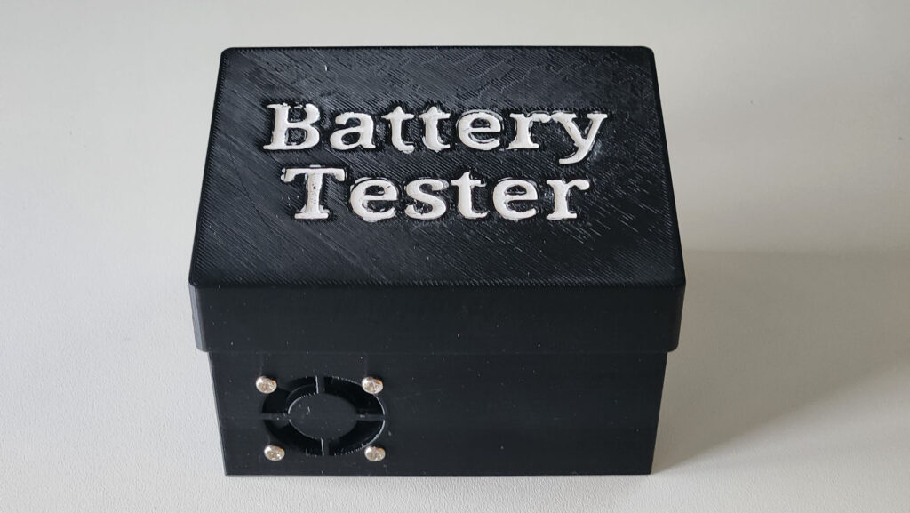
Finished set
Details worth noting when assembling:
- After testing the coolers connected to the circuit, I cut the socket board to make it as small as possible.
- To bolt the coolers so that one of them pulls are inside the chamber and the other pushes are outside. It doesn’t matter which direction, as long as both are working toghether to provide a flow of air around the heatsink fins. Also, Placing the screws in the innermost holes requires patience, as the nuts keep falling out of the finger trying to hold them in place.
- It is necessary to apply some CA glue (a.k.a. super-glue) in the recesses of the heatsink, otherwise it ends up moving a lot when trying to position the resistor cables through the hole in the bottom cover
- It is necessary to apply a some CA glue to the recess for the battery holder, on the top cover, as it cannot be screwed.
Finished Project
The finished assembly is intended to be used as is, without any top cover to hide the wires and part of the circuit board. I made this decision to reduce the complexity of the project, as it would require designing buttons, light conduits, so on, so forth.
Usage
To use the device, simply follow the steps described in the ZB2L3 Tester Circuit section, repeated in the slideshow below:
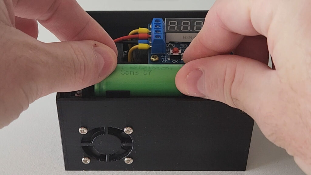
Insert the battery 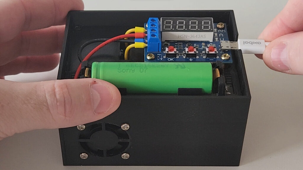
Connect the USB cable 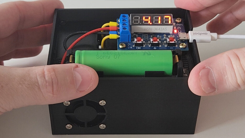
Check the inicial battery voltage (4.17V here) 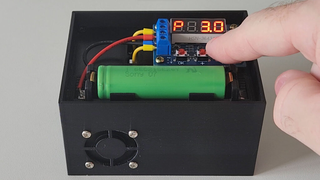
Set the cutoff voltage (3.0V is suggested) 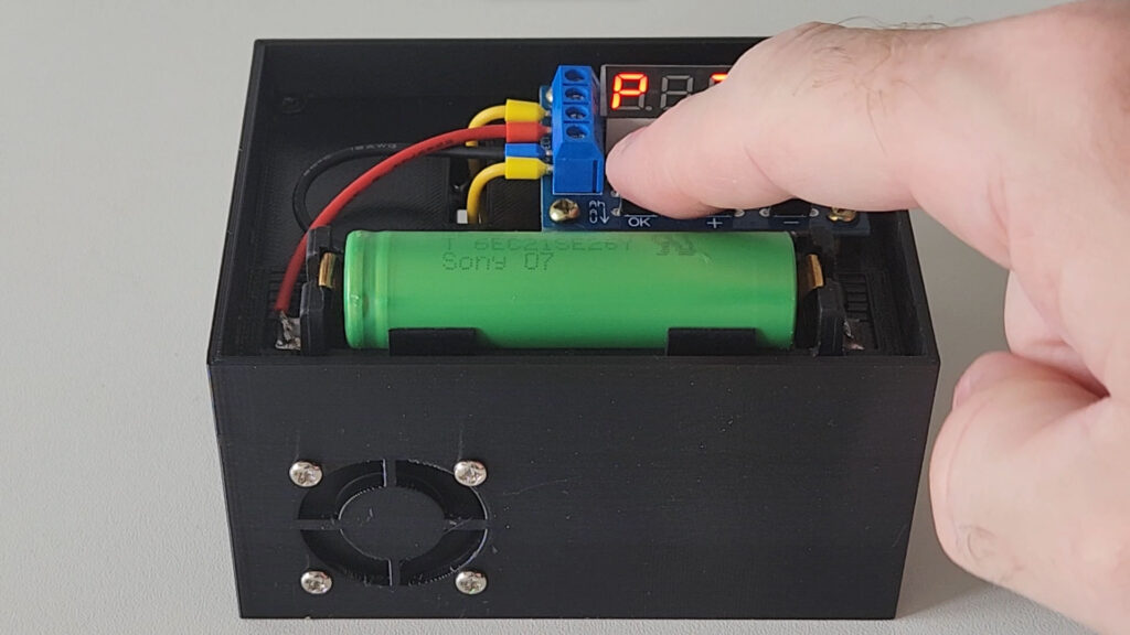
Start the measurement process 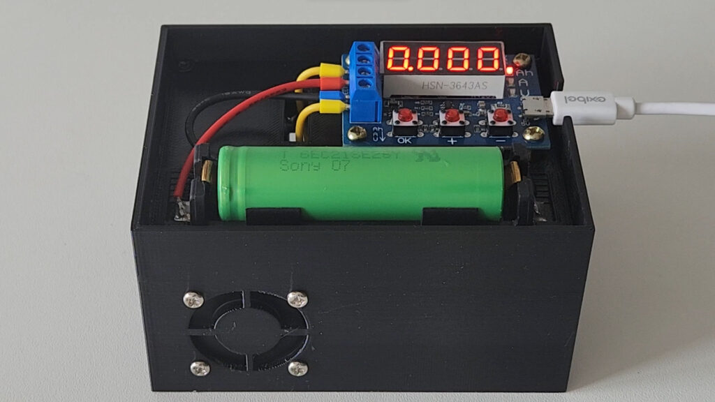
Initial measured capacity (0mAh) 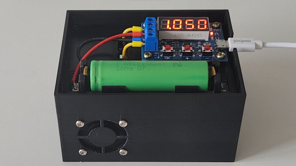
Current being drawn from the battery (1050mA) 
Initial voltage after starting the process 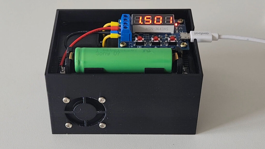
Final measured capacity (1501mAh)
Durante o processo de medição, será observado o seguinte:
- As soon as the process starts, the initial battery voltage instantly drops by 0.2V or 0.3V. This is normal, as under load, voltage from a power source usually drops.
- The current consumed gradually drops overtime
- The voltage, after the initial drop, starts to gradually decrease, however, for batteries in good condition, the tendency is for it to remain between 3.8V and 3.4V for most of the duration, until it starts to drop more quickly towards the cut-off voltage.
Final Thoughts
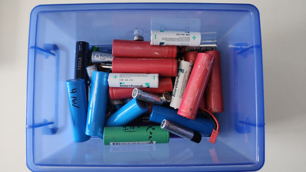
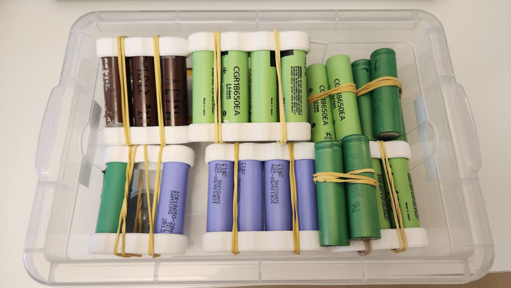
Using the tester, I was able to approximately establish the capacity of all batteries below, extracted from other devices, and which are still capable of holding a very good charge. Additionally, I tested 10 new batteries that I purchased for another project.
Approximately half of the batteries removed from old devices were in poor condition and not worth reusing, but the other half can easily be reused in projects that do not require a lot of current / capacity (some projects will be presented here in the future).
Bill of Materials
| ZB2L3 breakout circuit – 1 unit There are different test modules in this link, but ZB2L3 is the cheapest and simplest. | |
| Battery Holder for 18650 – 1 unit | 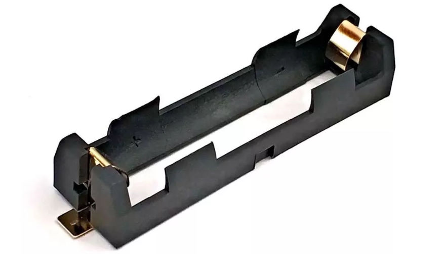 |
| Coolers 30x30x10 – 2 units For this project (in TinkerCAD), only these coolers will fit correctly. But if you make your own project, it can be any size. Ideally, the should be 5V in oder to use USB power. | 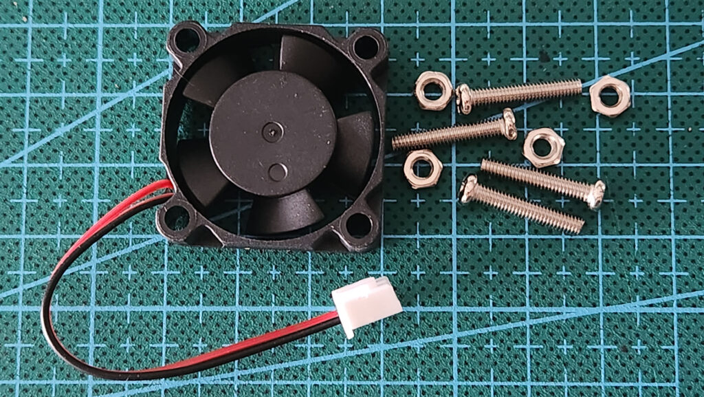 |
| Aluminium DN812K Heatsink – 2 units I could not find any item in AliExpress so, I linked the Brazilian e-commerce here for reference. Also, below, you can find the heatsink measures (in milimiters). 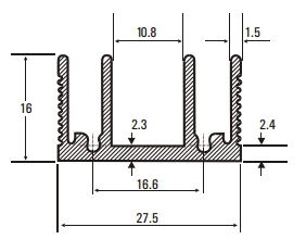 | 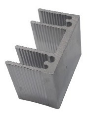 |
| M3 12mm wood screws – 4 units Used black screws to attach the top and bottom covers onto the main box | 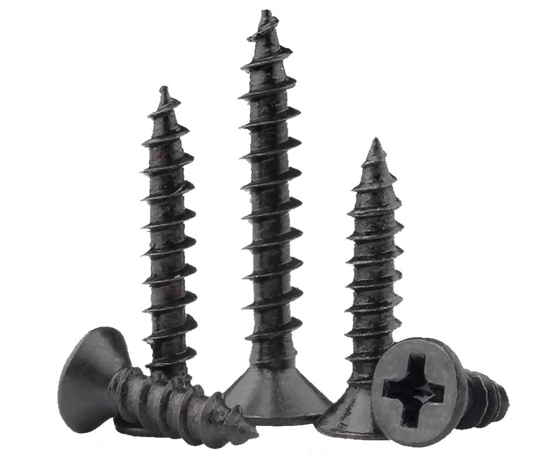 |
| M3 Allen 5mm Bolts – 4 units Used to attach the ZL2L3 circuit to the top cover. | 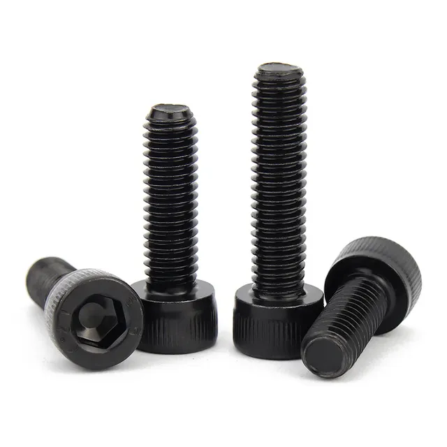 |
| 1.0 to 1.5 mm electrical wires – to handle 1A to 1.5A, which is the load imposed by the circuit. I used red (+) and black (-) to connect the battery and yellow to connect the resistors. | 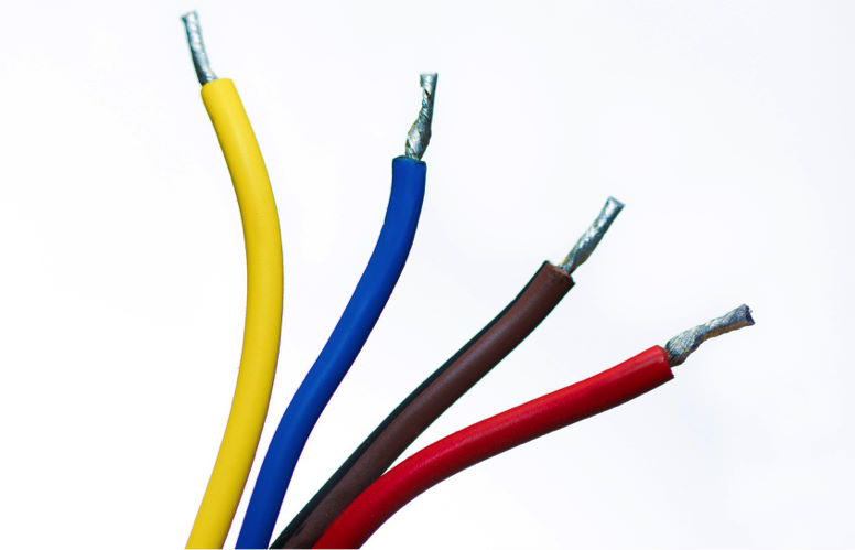 |
| Tubular Crimp Terminals – 4 units (3 colors) Entirely optional. I used them because they allow for a much better finish and reduce the risk of disconnection / poor contact. | 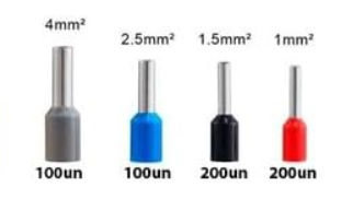 |
| Thermal Paste It is not extremely necessary, but advisable. Furthermore, the quantity required is very small, so if you are going to buy only for this, buy the smallest package you can. |  |
| Thin metal wire (0.7mm) Used to attach the heatsinks to the resistors. Wire of other gauges can also be used, as long as they are not too thick, as this will make it difficult to bend them around the heatsink. | 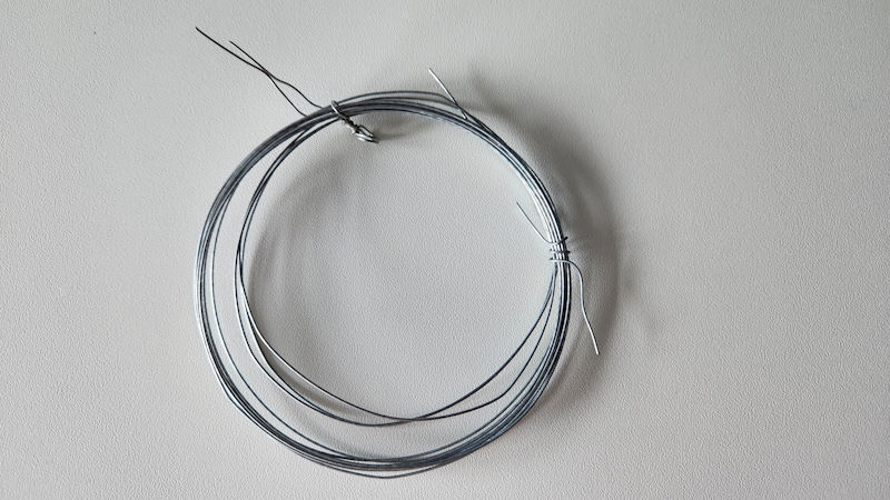 |